
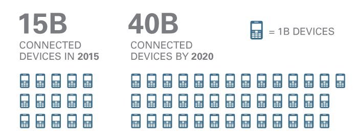
The number of Internet connected devices is growing dramatically, it is expected to increase from 15 billon devices in 2015 to 40 billion devices in 2020. These devices make up something called the Internet of Things. These devices can be controlled remotely and interconnected.
While a lot of these devices can be connected to the Internet, most of them are “dumb” devices right now. To turn these “dumb” devices into smart devices you can use the Internet of Things to connect them to the cloud. Simple things such as a washing machine or a coffee pot can be connected to the Internet. More practical systems can be connected also, such as a home automation system or a thermostat. Going even further a mine could connect safety sensors to the Internet of Things as well.
The Internet of Things allows for these devices to either be controlled or act as sensors and provides a means for them to communicate. This is done over a protocol called MQTT. According to mqtt.org, “MQTT is a machine-to-machine (M2M)/Internet of Things connectivity protocol. It was designed as an extremely lightweight publish/subscribe messaging transport.” This works great for many devices as-is, doesn’t have many dependencies, it is very lightweight, and doesn’t require tremendous amounts of processing power.
IBM Bluemix provides a platform for creating these apps that utilize all these sensors. You can basically almost use any programming language you want, Bring Your Own Language (BYOL) and utilize services that do the heavy lifting for you. This heavy lifting is the Internet of Things (IoT) service in Bluemix. It implements that MQTT protocol and allows you to control and receive data from these devices.

Do you have a bunch of left over Christmas lights sitting around that will be collecting dust till next year? Until now Christmas lights are a once a year thing, that isn’t true anymore. Time to get the dust off of your lights and use them for something fun! Enter Christmas Lights controlled by a Raspberry Pi via IoT in Bluemix!
You can control these Christmas Lights using the Internet of Things and IBM Bluemix. Who doesn’t love large amounts of Christmas lights? I sure love them. Add on to that syncing lights to music and the ability to control lights from your phone and giving passersbys the ability to vote for songs they wanna see the lights synced to by texting. How cool is that?
Introduction:
This is going to be a three part series: The first part (this post) will focus on the hardware setup, all the wiring and connecting things up to the Raspberry Pi. The second part will focus on the software configuration of the Raspberry Pi, and the final part will focus on the Bluemix app that allows people to vote on songs to play and the integration to control the Raspberry Pi with the IoT service in Bluemix.
So some of our goals that we are going to accomplish are the following.
Part 1 – Setup and wire together relays, outlets, and the Raspberry Pi
Part 2 – Power on the Raspberry Pi, installed Raspbian (OS for the Pi), install and configure the lighting control software
Part 3 – Deploy a Bluemix app with the IoT, Twilio, and Cloudant services to interact with users and the Raspberry Pi (an example of the app is http://lights.mybluemix.net/; please note this is not connected to my Raspberry Pi right now, so clicking the play button won’t do anything.)
Here is a little teaser of the expected outcome:
Let’s jump into it…
Part 1: Setting up the hardware
These instructions have been adapted from the following sites.
https://docs.google.com/document/d/1x97JIu5xVInZMutTNeaHlnQuyoLHjf3h-ugIo64pGfI
http://lightshowpi.org/configuring-and-testing-your-hardware
The first step is getting a Raspberry Pi, I highly recommend getting the CanaKit on Amazon. It comes with most of everything you will need. Depending on how fancy and clean you want your wiring to look you will need to take a trip to your local hardware/electrical store, more on that later.
The first step is deciding how many individual light channels you want—you can do up to 48 actually, but for this post we will doing 16 channels. What that means is 16 individual strands of lights that can be controlled. So let’s make a shopping list.
Shopping List:
2 relays (1 relay per each 8 light channels, available on Amazon)
Tools Required:
My brother (@esloyer) helped me wire this whole thing up and came up with an adapted wiring schema based off the sites above, thanks bro!
Once you get all the items on the shopping list we need to start taking apart the 50 feet of wire, there is 2 wires inside of the casing, a black and then a white one. We need to get them out of the casing, take a pocket knife or utility knife and make a cut into the casing at one end, you can basically then peal back the casing on the whole 50 feet of wire then.
Below is a wiring diagram that we need to complete. You can do this multiple ways but below is a suggestion.
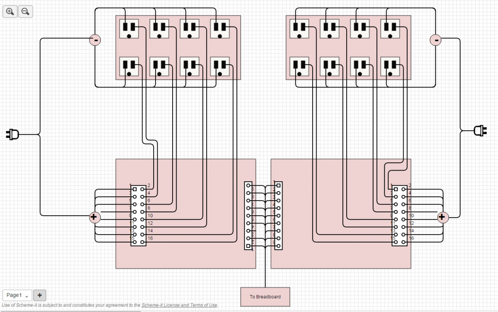
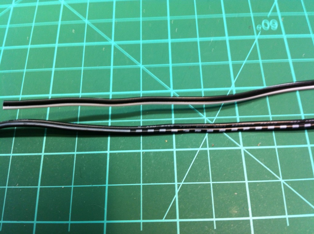
What we need to do is basically daisy chain all the “hot” wires together between each set of 4 gang double gang outlets. We do this so we don’t overload a particular circuit. So to do this we need to cut the end off of our cheap extension cord that has a plug on it, we need to then strip the wires, and then identity which wire is the hot/positive wire. Below is a picture of a wire, the hot/positive wire will have dashes or stripes on it, the cold/neutral wire will NOT have any dashes or stripes:
We need to take the hot wire and put it into a wire nut. We will then take some wire from our 50 feet, strip one of the ends and twist it into the wire nut. This will get attached to positive input on the relay. We need to repeat this for each channel. In the picture below I have an additional wire going from the first wire nut to another wire nut because all the wires going to the relay wouldn’t fit into one wire nut. We are just effectively connecting two wires together here.
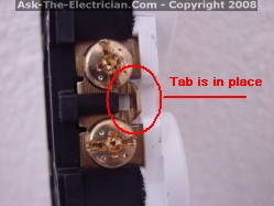
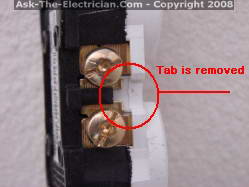
The next step is running a wire from each channel on the relay to electrical outlet. This is the hot wire to each outlet but this wire is being controlled by the relay. Think of the relay as a simple on/off switch that you would find at home to control a light. On most double electrical outlets there is a tab on the side that comes enabled that makes most receptacles operate as one, this is desirable in a house so an electrician only has to run one wire to the outlet but in our case we want to take advantage of controlling both receptacles. We need to break this tab on both sides of the outlet. Take a pair of needle nodes pliers and bend the tab back and forth and eventually it will come off. See the photos below.
Before:
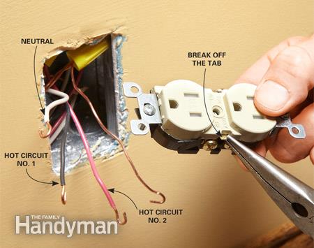
After:
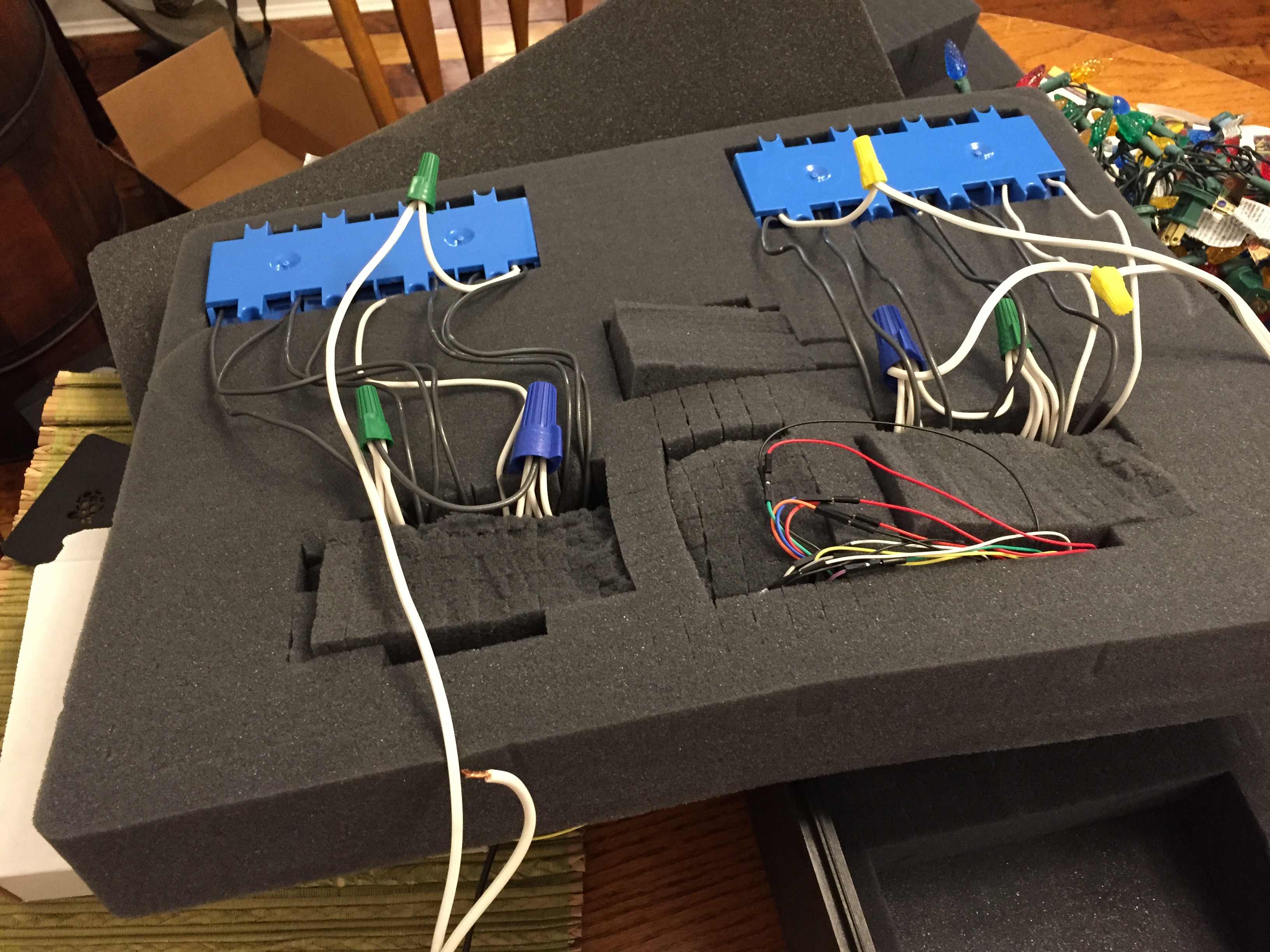
So next we need to connect our cold/negative wires to each of the outlets. If you look at the wiring diagram (above) I have one cold/neutral wire going to the first outlet and each additional outlet is daisy chained to it. This is just to complete the circuit. Below is the finished product. We basically have our outlets daisy chained together with our cold/neutral wires and then hold/positive wires have individual channels to the relay.
Congratulations the hard part is over! Well, at least for me, since electrical stuff isn’t my forte.